
Sequence of execution #
The execution of an action consists of consecutive executions of nodes that are connected by a Sequence connection (white-colored). By connecting nodes with Sequence ports, we set the sequence in which these nodes should be executed. The first node in each action is always the Start node. Next, the node that is connected by the input Sequence port to the output port of the Start node is executed, and after that – the next node, which is connected by its input Sequence port to the output Sequence port of the previously executed node, and so on.
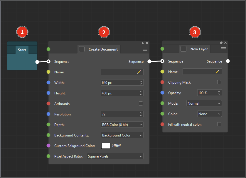
In the algorithm in the picture above, the first node to be executed is the Start (1) node, which essentially does nothing and is an auxiliary node that indicates the start of the algorithm. The next node will be the Create Document node (2), which will create a new Photoshop document with the specified parameters. After the document is created, the New Layer node (3) will be executed (which will create a new layer in the document created by the previous node), since it is connected by the Sequence input port to the Sequence output port of the Create Document node (2).
Branching of execution #
Unlike Photoshop actions, ActionNodes can automatically change the sequence of execution depending on certain conditions. To do this, ActionNodes have flow control nodes.
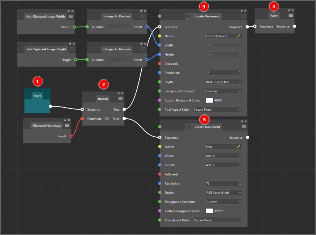
For example, in the screenshot above, after the action starts, execution proceeds to the Branch (2) node, which has two output Sequence ports (True and False). So where will the algorithm go next? It all depends on the value in the Condition parameter of the Branch (2) node: if it is true (checked), then execution will be performed over the True connection, if false (unchecked), then over the False connection. Since the Clipboard Has Image node is connected to the Condition parameter of the Branch (2) node, the value of this parameter will be taken from this node, and it, in turn, returns true if the copied image is on the clipboard and false if it is not. So, if there is a copied image on the clipboard, the execution sequence will go through the True output of the Branch (2) node to the top Create Document (3) node, and then, since it has only one Sequence output port, to the Paste (4) node.
If there is no copied image on the clipboard, then the Clipboard Has Image node will return false, and execution will go to the output Sequence port False of the Branch node (2) and, accordingly, to the lower Create Document (5) node connected to this port.
Switching execution #
In some cases, you may need to select one of many execution sequences based on some numeric value (or string). This can also be accomplished by using multiple Branch nodes. But it is much more convenient and more compact to do this with switch nodes. Switch nodes are dynamic nodes, that is, the number of input/output ports can be changed dynamically.
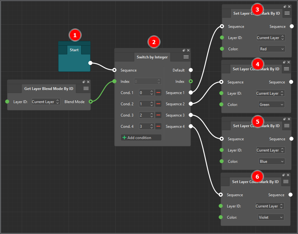
The example above uses the Switch by Integer (2) node, which is executed immediately after the algorithm starts. Then this node checks the value of the Index parameter and, based on this, determines which of the conditions this value corresponds to. If the value corresponding to the Index parameter is found, then the output port of the sequence type corresponding to this value is selected and execution continues along the sequence of nodes (3, 4, 5, or 6) connected to this port. If the Index parameter does not meet any of the listed conditions, then the sequence of nodes connected to the Default output port is executed.
In this case, we are not checking the value of the Index parameter, but the value of the Blend Mode output port of the Get Layer Blend Mode By ID node connected to the Index parameter.
Looping of execution #
Sometimes, in addition to branching, you may need to repeat some node sequences. For this purpose, loop nodes exist. These nodes have two output Sequence ports: Loop Body and Completed.
After execution moves to the loop node, the next step is to check the loop condition. If the conditions are met, then execution moves to the node connected to the Loop Body output Sequence port. After that, execution continues from node to node until the chain of nodes connected by the Sequence connection ends. Then execution will return to the loop node again. The cycle execution conditions are checked again, and if the check is successful, the chain of nodes connected by the Sequence connection to the output port Loop Body of the loop node will be executed again. And so on. The execution will repeat until at some point the loop condition check fails. Then the execution of the loop will be completed and the next node will be the node connected to the Completed output port of the loop node.
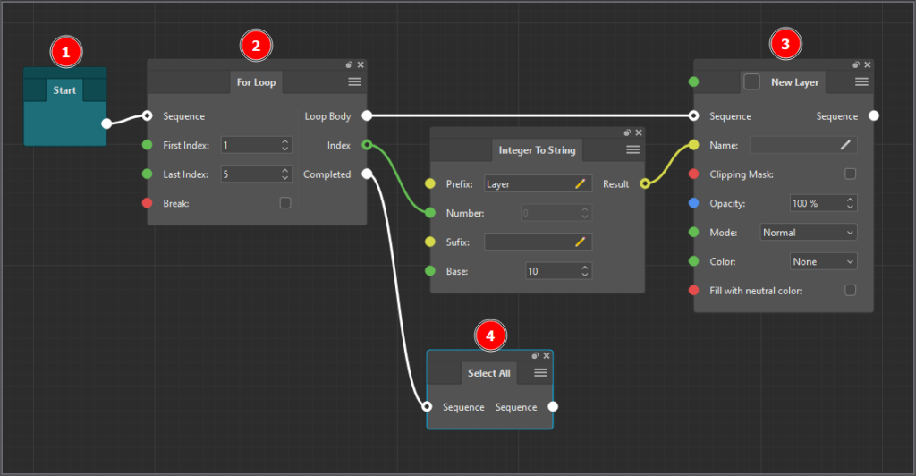
In the image above, after the Start (1) node, execution proceeds to the loop node For Loop (2). The For Loop node executes a loop (New Layer (3) node) by incrementing the internal loop counter by one from First Index to Last Index until this counter becomes greater than Last Index. After the fifth execution, the loop node condition check will fail and the next node to execute will be the node connected to the Completed Sequence output port, which is the Select All (4) node.
Connection looping
Keep in mind that you cannot loop a connection in ActionNodes. That is, you cannot connect the output of any node through any number of consecutive nodes to the input of the same node.
Nodes without Sequence ports #
ActionNodes have some nodes that do not have ports of the sequence type. Such nodes cannot be directly placed in execution sequences, because by their logic they are auxiliary nodes that connect to the parameters of other nodes. By connecting them to the input parameters of other nodes, you give such parameters the ability to receive values from other sources. For example, by attaching a Get Value node where you select a variable to the input parameter of some node, you will bind this parameter to the value of the selected variable.
Please note!
Although the Get Value node for getting the value of a variable does not have ports of the sequence type, the Set Variable node for setting the value to the variable does. Therefore, to set the value of a variable, you need to place the Set Variable node in any sequence of nodes so that the value you need is set. And to use the set value, you must make sure that Get Value node is used in the node that comes after the corresponding Set Variable in the execution sequence.


